Prove multiasse

Home » By Test Type » Multi-axis testing

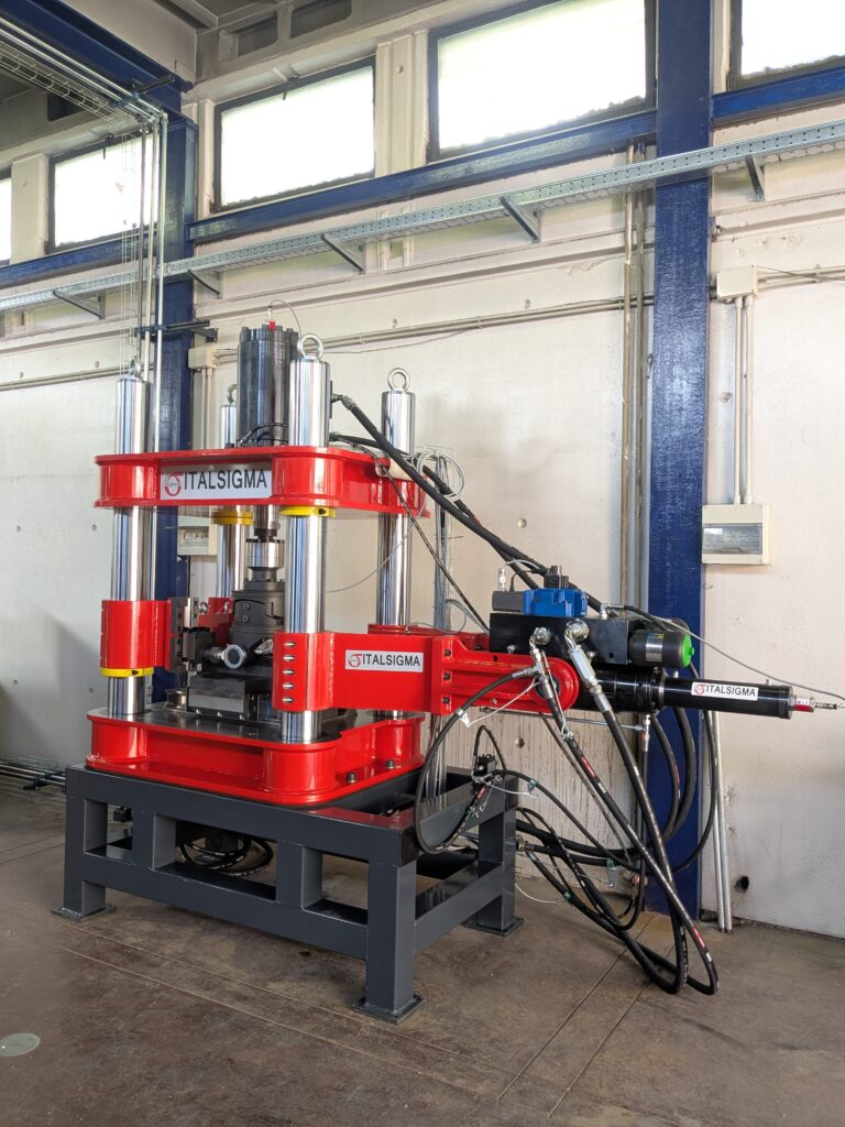
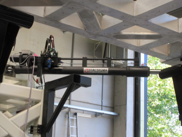
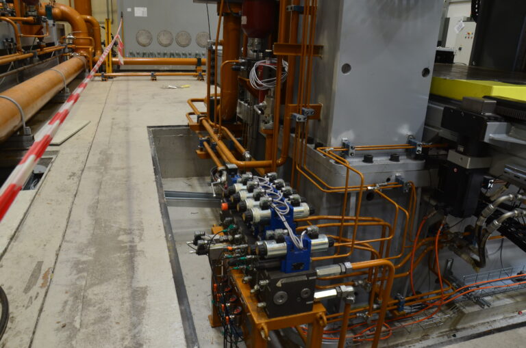
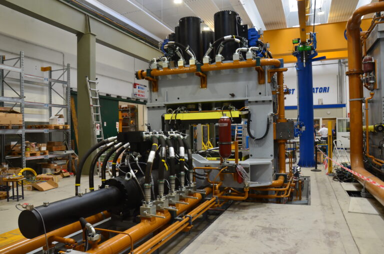
Multi-axis tests are advanced structural tests that apply simultaneous loads in different directions (axes) to a component or material. Unlike uniaxial tests, these simulate complex real-world operating conditions, evaluating fatigue strength, durability, and three-dimensional deformation—all of which are crucial for critical components such as rotors or structural parts.

Key Details:
  • Purpose:

    To verify the fatigue strength and durability of materials under real-world loads, preventing unexpected failures.

  • Application:

    These tests replicate real-world stresses on components—such as helicopter tail rotors—on the ground, ensuring compliance with flight certifications.

  • Technology:

    They use servoactuators or biaxial/triaxial testing systems capable of applying forces and torques simultaneously.

  • Sectors:

    Aerospace, automotive, and materials engineering.

These tests are essential for validating computational models during the design phase, ensuring that materials withstand millions of load cycles.

PROJECTS:

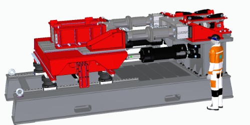
  • X-2002-1000 – Biaxial Testing Machine

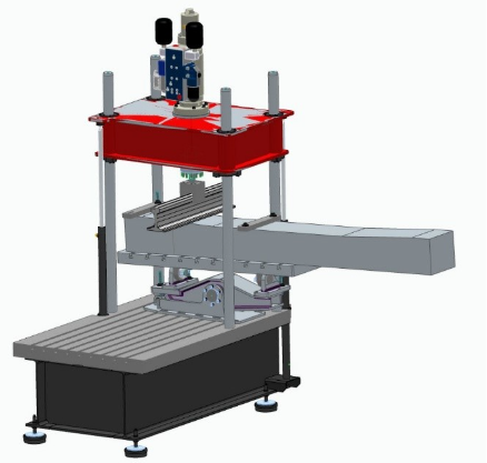
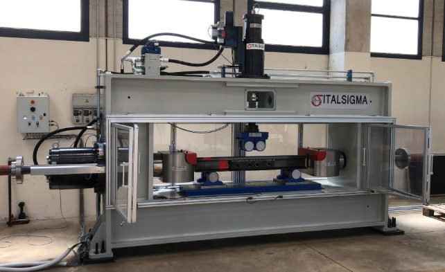
    X-2002-1000 Biaxial Testing Machine for Dynamic Testing of Railway Sleepers, subjected to tensile loading along the horizontal axis and simultaneous three- or four-point bending along the vertical axis. Load Frame Closed-loop load frame consisting of a fabricated steel structure comprising a lower working platform, four vertical reinforcing structures and an upper crosshead on which the vertical actuator is mounted. Frame dimensions: 3,600 × 6,100 × 4,350 h mm
    • Maximum static force: 1,200 kN at 210 bar
    • Maximum dynamic force: 1,000 kN at 210 bar
    • Vertical force: 500 kN
    • Horizontal actuator stroke: 250 mm
    • Maximum vertical specimen clearance: 800 mm
    • Maximum horizontal specimen …
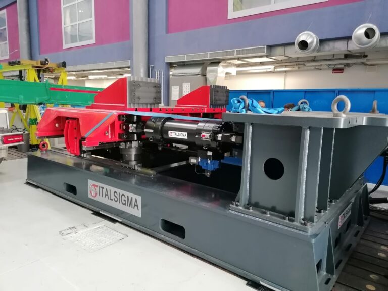
  • BX0316 – Biaxial Testing Machine

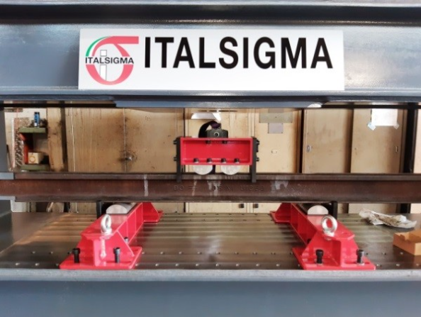
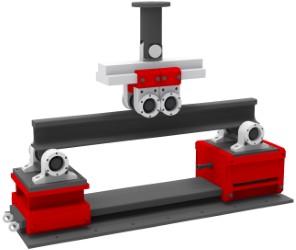
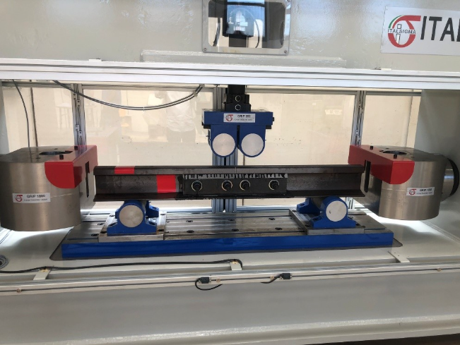
    BX0316 Biaxial Testing Machine for Static Tensile and Dynamic Four-Point Bending Tests on Bonded Rail Joints
    • Tensile testing with horizontal loads of up to 1,600 kN
    • Bending testing with vertical loads of up to ±350 kN
    • Standard horizontal actuator stroke: 200 mm
    • Standard vertical actuator stroke: 100 mm
    • Fatigue testing fixture with adjustable supports within predefined ranges
    • Maximum rail length under test: 1,600 mm
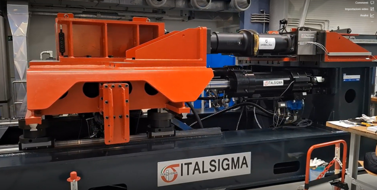
  • Indoor Test Bench for Railway Vehicle Traction and Coupling

    Indoor Test Bench for Railway Vehicle Traction and Coupling

    Indoor testing bench for measuring traction and coupling forces between railway vehicles. TECHNICAL SPECIFICATIONS
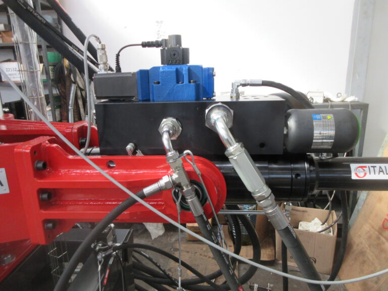
    • Maximum longitudinal tensile force: 1,150 kN
    • Maximum longitudinal compression force: 1,150 kN
    • Lateral force applicable to the frame: ±100 kN
    • Moment applicable to the frame: ±500 kNm
    Maximum-performance stroke:
    • X = 500 mm
    • Y = 900 mm
    • θ = ±15°
    Translation speed along the X-axis: 0.25 m/s Translation speed along the Y-axis: 0.60 m/s Rotation speed about the Z-axis: 10°/s
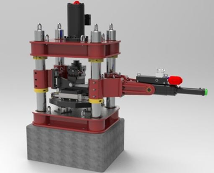
  • BX2112 – Servo-Hydraulic Testing System

    Testing system for the characterization of sliding materials.

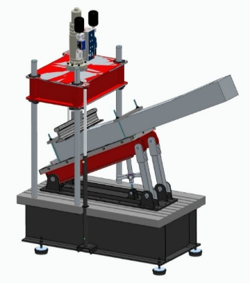
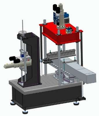
    The Italsigma BX2112_1P is designed to determine the coefficient of friction between sliding elements used in structural bearings, in accordance with EN 1337-2:2002, Annex D. TECHNICAL SPECIFICATIONS
    • Vertical load: 500 kN
    • Horizontal load: 100 kN
    Main components:
    • Four-column frame designed to withstand a vertical load of 500 kN with high structural rigidity.
    • Vertical actuator capable of applying a compression force of 500 kN at 210 bar, with a 100 mm stroke. The actuator is equipped with a servo valve and an LVDT transducer for piston displacement measurement.
    • Force transducer for measuring the …
  • Rail Fastening System Testing Machine

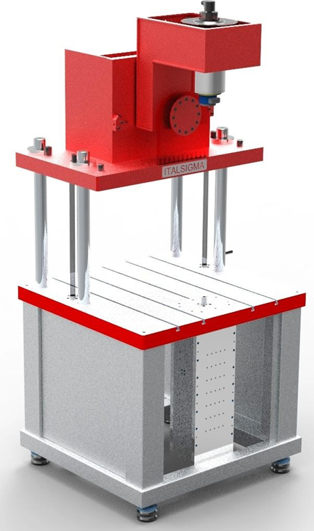
    Testing system designed for the characterization of rail fastening systems.

    The system is designed to perform the following tests:
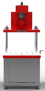
    • Determination of the longitudinal rail resistance, in accordance with UNI EN 13146-1
    • Determination of the torsional resistance of the rail, in accordance with UNI EN 13146-2:2012
    • Determination of the rail clamping force and uplift stiffness, in accordance with UNI EN 13146-7
    • Determination of stiffness, in accordance with UNI EN 13146-9
    • Determination of pull-out resistance, in accordance with UNI EN 13146-10:2017
  • Ortho 3 – 3-Axis Biomechanical Simulator

    Three-axis biomechanical simulator for orthopaedic prostheses.

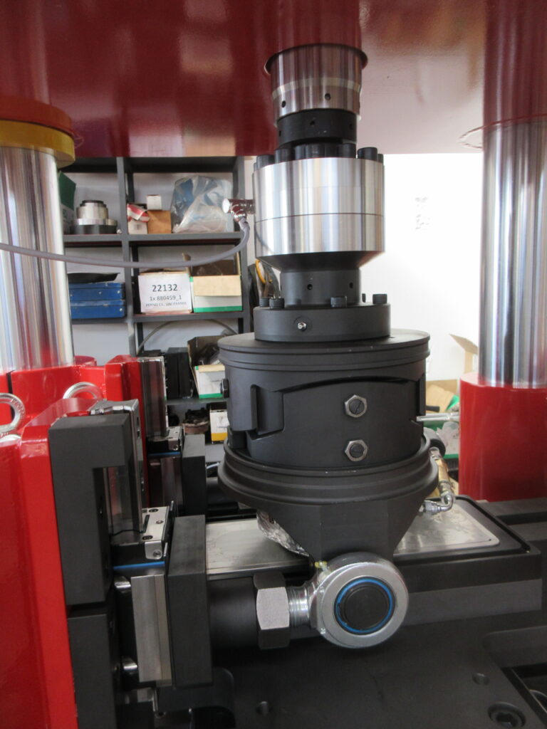
    The machine features a four-column frame with an electric actuator mounted beneath the lower crosshead. The load cell can be mounted either on the lower or upper test surface. Equipped with a 6-axis load cell measuring Fx, Fy, Fz, Mx, My and Mz. TECHNICAL SPECIFICATIONS
    • Vertical force: 10 kN
    • Axial moment: 100 Nm horizontal / 100 Nm vertical
    • Very high dynamic performance in the vertical direction
  • Seismic Simulation Testing Structure

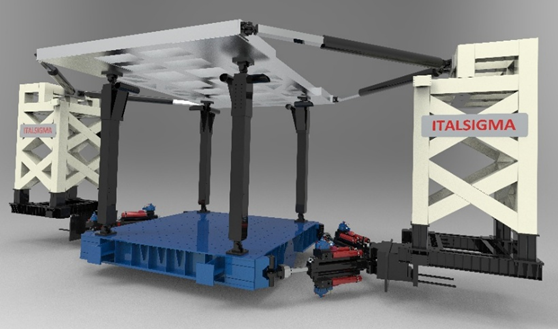
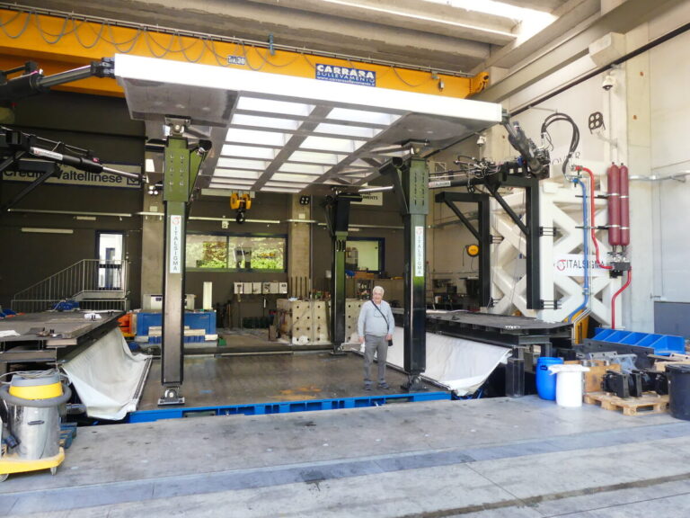
    Large-scale experimental testing system for dynamic testing of structural and non-structural components.

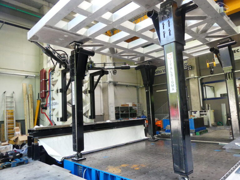
    The system consists of four actuators and is capable of simulating the relative response of any pair of adjacent floors in buildings of any height. TECHNICAL SPECIFICATIONS
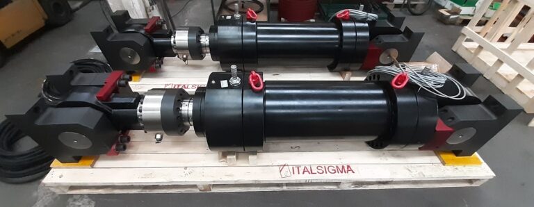
    • Nominal operating pressure: 280 bar
    • Displacement capacity: ±1,000 mm
    • Force capacity: ±150 kN
    • Spherical joints: 150 kN
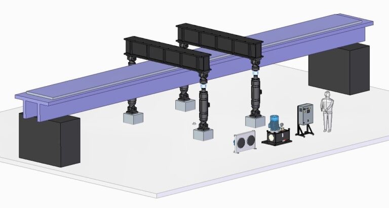
  • Viaduct Beam Testing System

    Testing system consisting of four servo-hydraulic actuators with a total capacity of 6,000 kN (1,500 kN per actuator), a hydraulic power unit and a control system.

    TECHNICAL SPECIFICATIONS
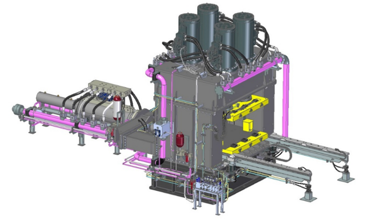
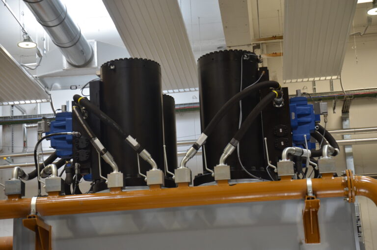
    • Vertical force: 6,000 kN
  • BX112 – Biaxial Seismic Isolator Testing Machine

    Testing machine designed for testing seismic isolators.

    TECHNICAL SPECIFICATIONS
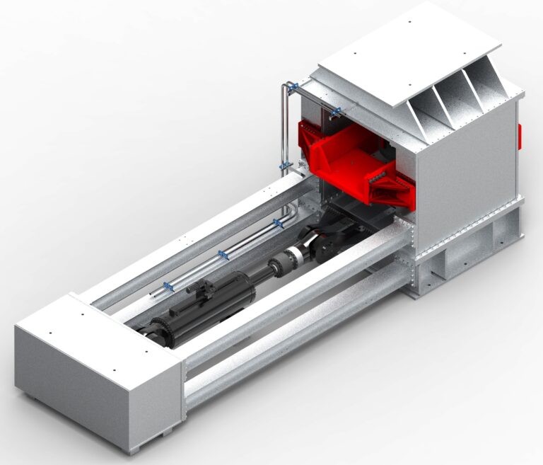
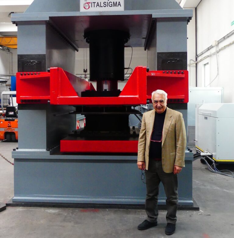
    • Vertical load: 30 MN
    • Horizontal load: 3,000 kN
    • Horizontal stroke: 1,000 mm
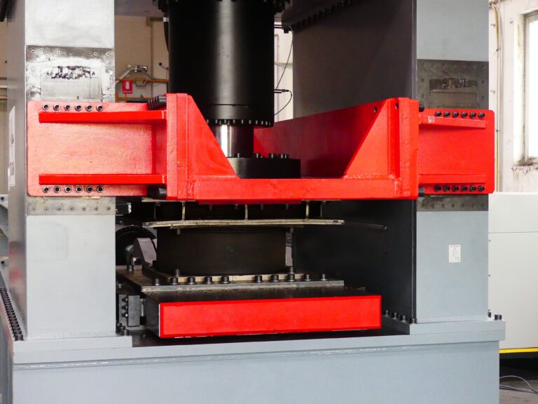
  • BX5528 – Biaxial Testing Machine

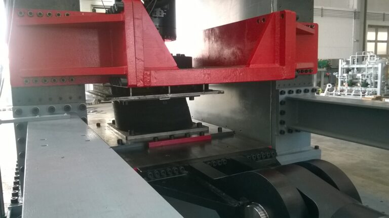
    The testing system is designed to evaluate the performance of elastomeric seismic isolators.

    The tests involve applying a compressive load in the vertical direction while imposing cyclic horizontal displacements. TECHNICAL SPECIFICATIONS
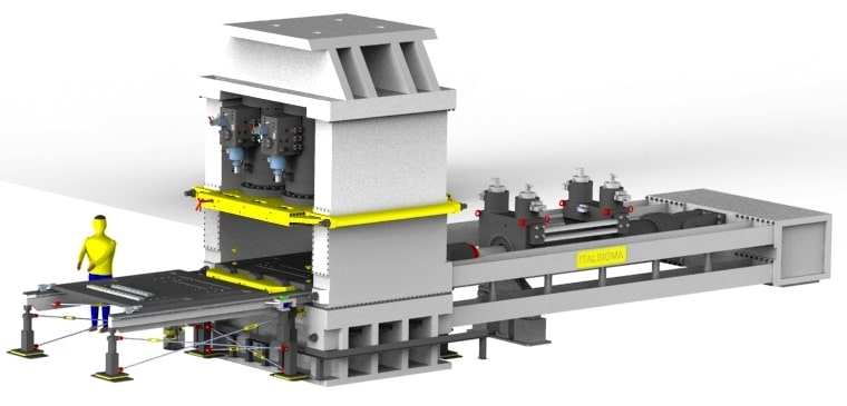
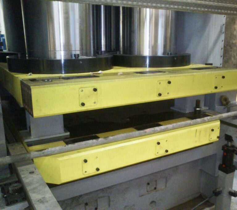
    • Vertical force: 5,500 kN
    • Horizontal force: 2,800 kN
  • BX30030 – Biaxial Testing Machine

    The testing system is designed to evaluate the performance of seismic isolators.

    The tests involve applying a compressive load in the vertical direction while imposing cyclic horizontal displacements. The machine's general performance specifications in terms of vertical and horizontal load, displacement and speed have been defined to cover the vast majority of end-of-production tests and most qualification tests. TECHNICAL SPECIFICATIONS
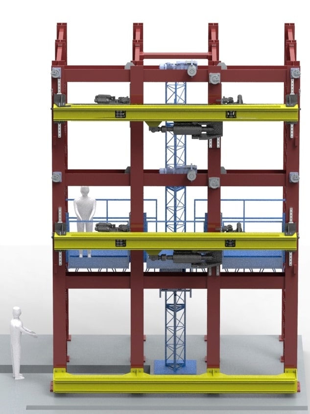
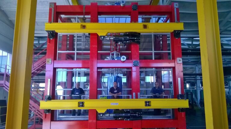
    • Vertical force: 30,000 kN
    • Horizontal force: 3,000 kN
  • Scientific Testing Equipment for Curtain Walls

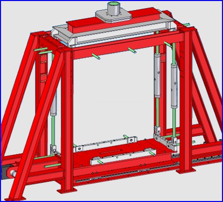
    In addition to the traditional air, water and wind tests required for the certification of curtain wall systems, the mechanical testing system allows the seismic response of curtain walls to be evaluated under both static and dynamic conditions.

    The system is equipped with seismic actuators capable of applying in-plane and out-of-plane loads to the curtain wall assembly. The system is suitable for:
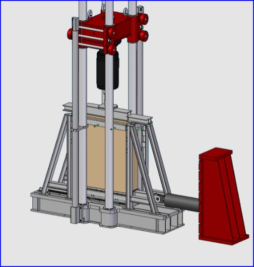
    • Air and water tightness testing
    • Static and dynamic uniaxial and multiaxial loading tests
    Tests can be performed on curtain wall systems with maximum dimensions of 6 × 8 m.
  • Wall-Constrained Load Frame

    The system consists of a semi-underground foundation connected to a frame for applying vertical loads.

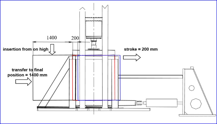
    The loading base is equipped with four roller bearings. The lower edge of the wall rests on the roller bearings, allowing the application of shear forces to produce controlled wall distortion. The maximum vertical load is 500 kN. To facilitate installation, the wall is inserted from above and then transferred into its final position using the roller-bearing system.
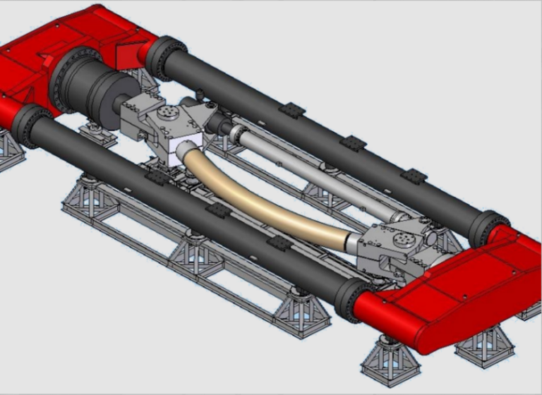
  • 30 MN FULL-SCALE TESTING MACHINE

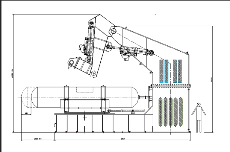
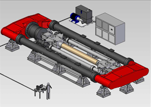
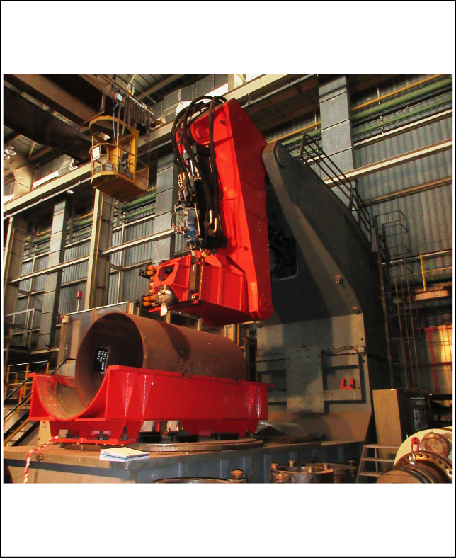
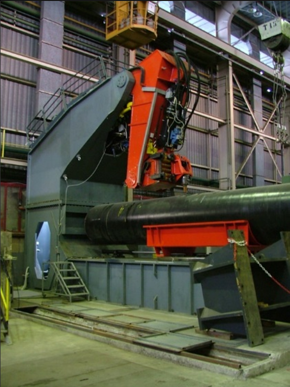
    This testing machine performs tensile, compression and bending tests on steel pipes for gas and oil pipelines.

    The system is optimized for specimen positioning and securing, and can perform cyclic tests as well as tests on pressurized pipes. TECHNICAL SPECIFICATIONS
    • Maximum compression force: 30 MN
    • Maximum tensile force: 25 MN
    • Maximum bending moment: 300 ton·m
    • Maximum specimen diameter: 20" (508 mm)
    • Maximum specimen length: 5,000 mm
    • Overall dimensions: 16 × 6 m – height 2 m
    • Maximum axial stroke: 500 mm
    • Maximum bending angle: ±20°
  • FULL-SCALE DAMAGE SIMULATION TESTING MACHINE

    This testing machine simulates damage caused by the bucket of an excavator or other construction machinery on steel pipes used for gas and oil pipelines.

    The damage is simulated through the impact of a steel striker at controlled speed and along a controlled trajectory. TECHNICAL SPECIFICATIONS

    • Pipe diameter: 24" – 36" – 48" – 52"
    • Maximum pipe length: 6,600 mm
    • Maximum impact velocity: 5 m/s
    • Striker-to-pipe impact angle: 0° to 90°

Would you like more informations?

Dosi Costruzioni Meccaniche

Holding Company

Baruffaldi Plastic Technology

Sister Company

©2026  ITALSIGMA S.r.l. Via Masetti, 50 – 47122 Forlì (FC) ITALY

P.IVA IT01763520408 | C.F. 01763520408 | Privacy&Cookie Policy | Credits: Wizard srl