
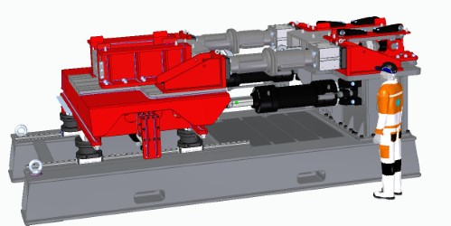
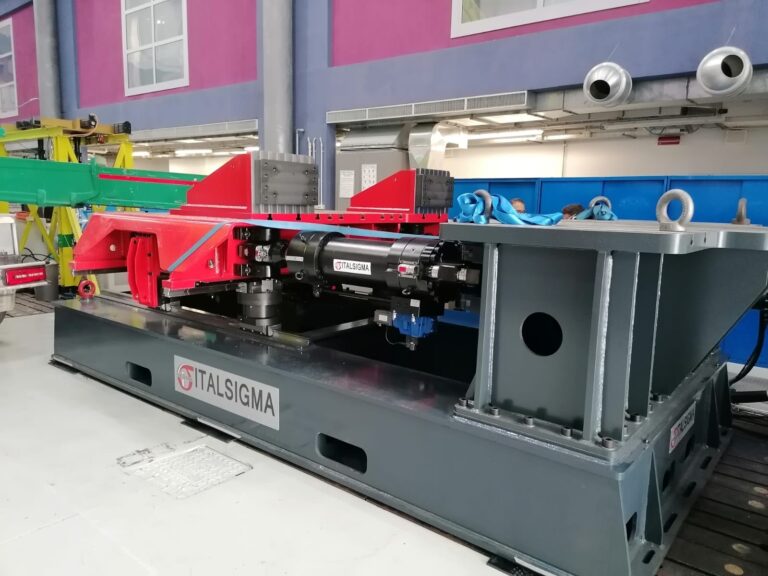
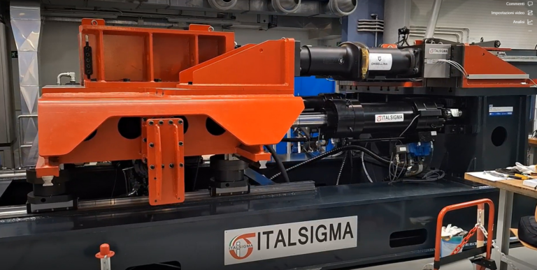
Indoor Test Bench for Railway Vehicle Traction and Coupling
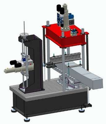
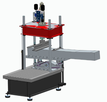
Indoor testing bench for measuring traction and coupling forces between railway vehicles. TECHNICAL SPECIFICATIONS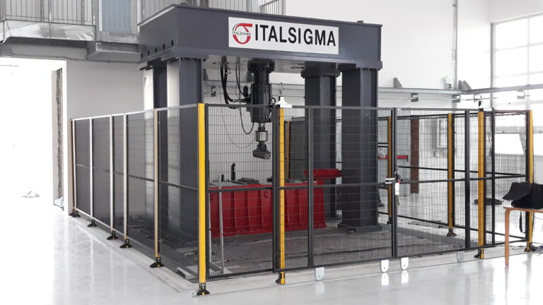
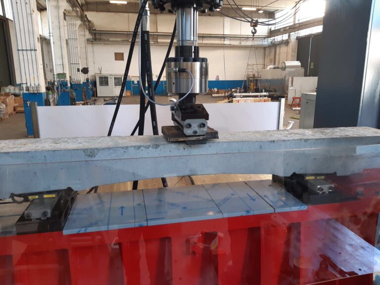
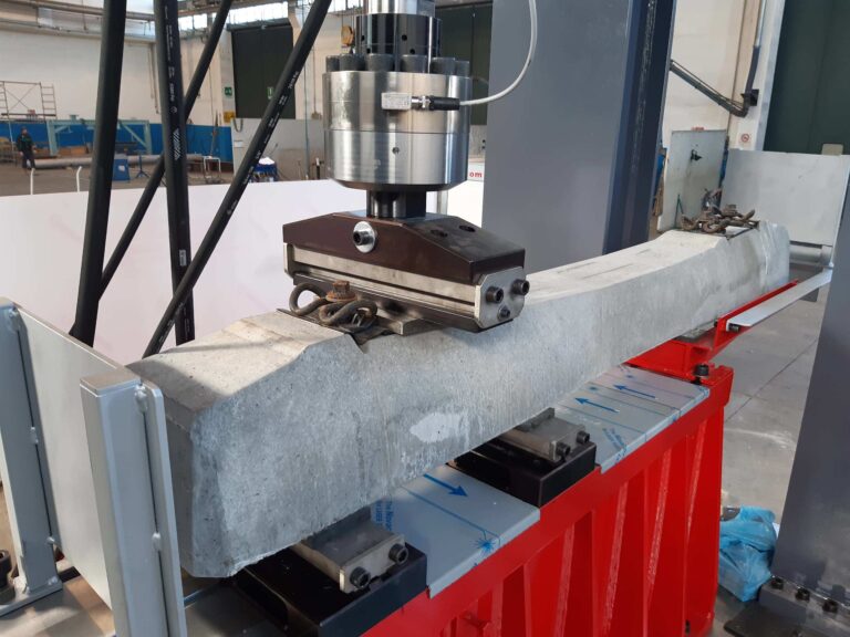
FATIGUE TESTING MACHINE FOR RAILWAY SLEEPERS
Four-column load frame (6,100 × 3,800 × 3,800 h mm).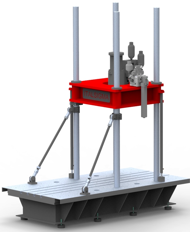
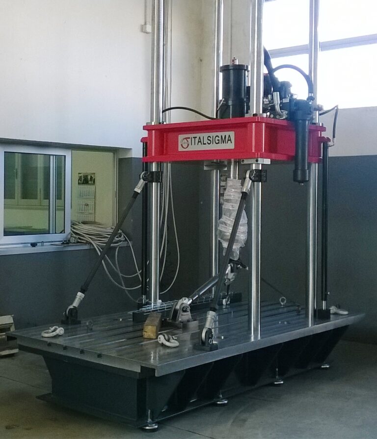
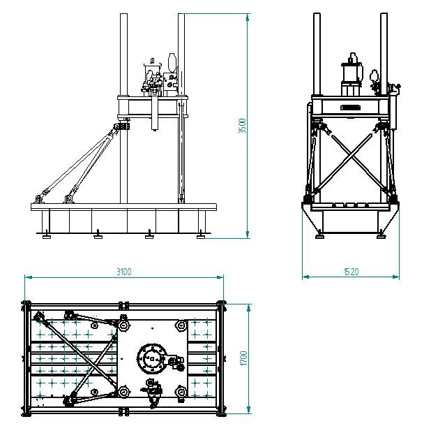
Four-column testing machine equipped with lateral column reinforcements, designed to withstand test loads up to 500 kN without significant deformation.
The base features a slotted test surface for securing testing fixtures and equipment.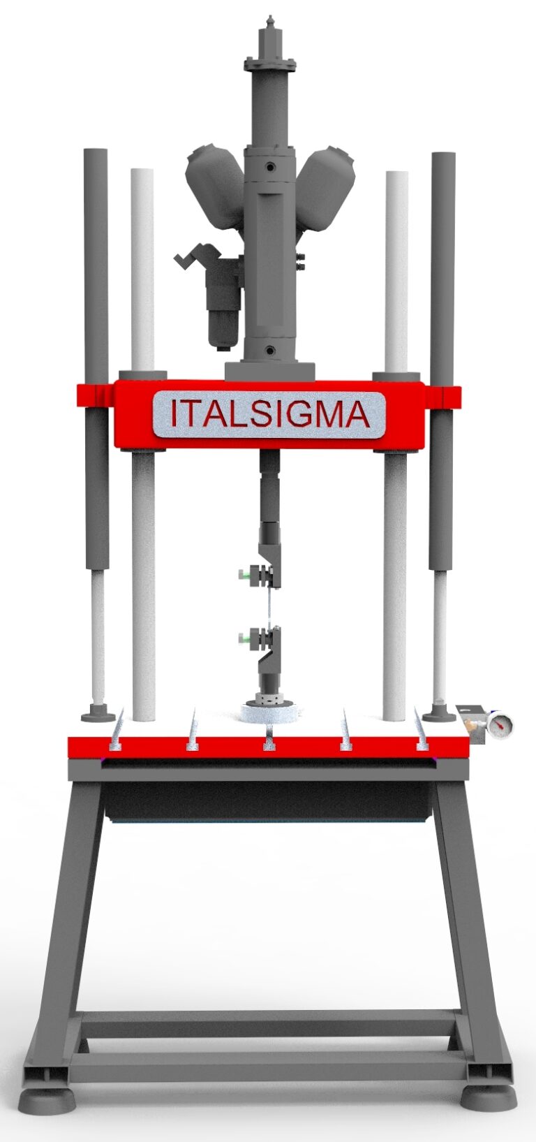
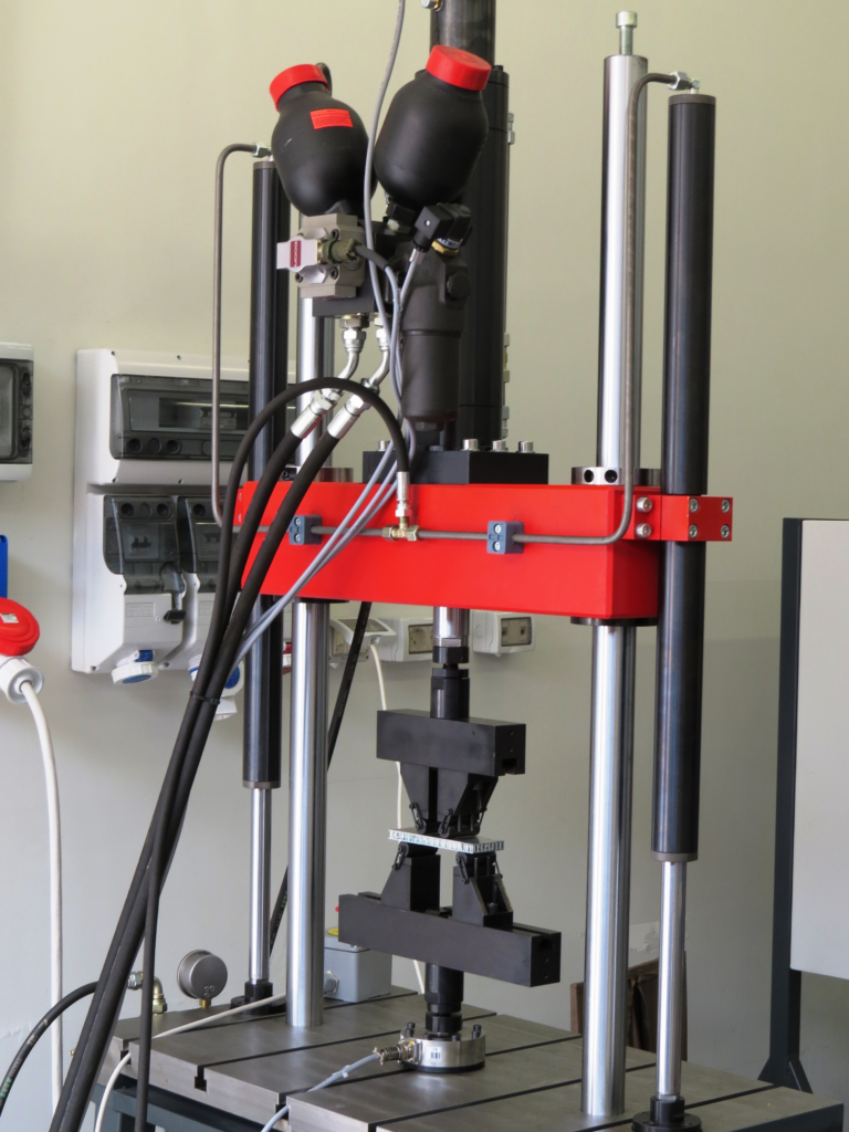
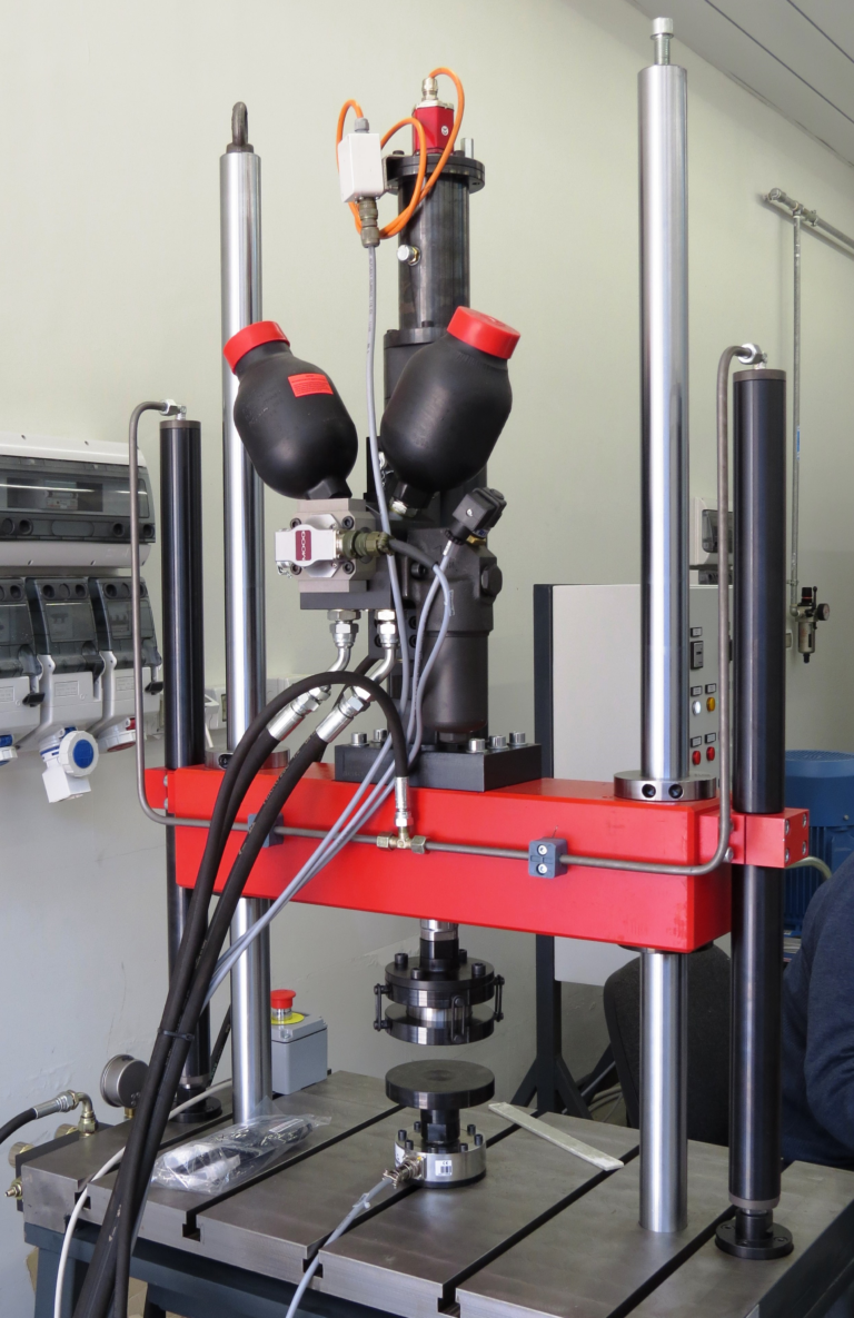
Two-column testing machine equipped with a servo-hydraulic actuator mounted above the upper crosshead and a slotted support base.
The load cell can be mounted either on the actuator or on the lower crosshead.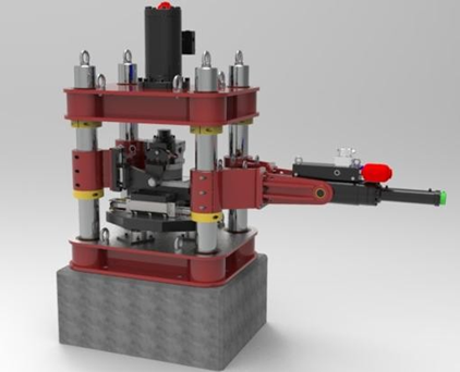
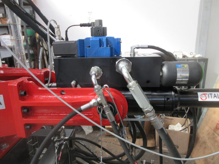
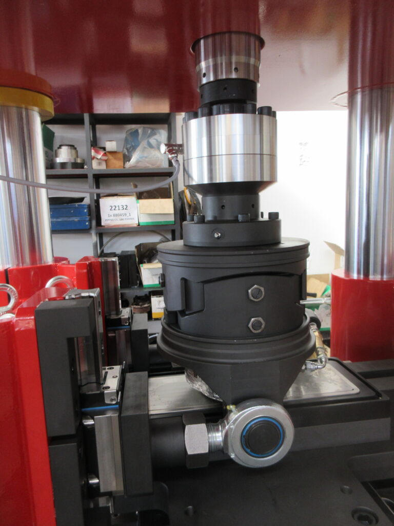
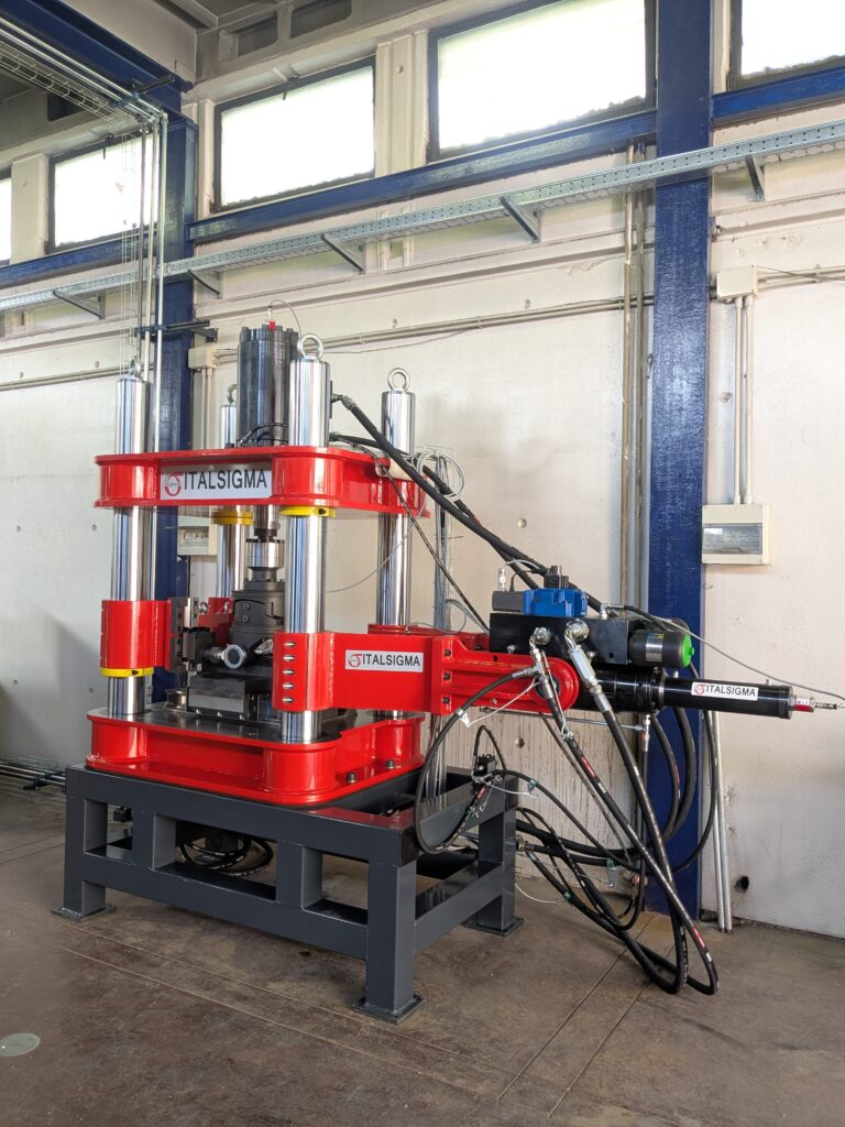
Testing system for the characterization of sliding materials.
The Italsigma BX2112_1P is designed to determine the coefficient of friction between sliding elements used in structural bearings, in accordance with EN 1337-2:2002, Annex D. TECHNICAL SPECIFICATIONS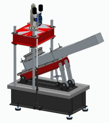
Testing system designed for the characterization of rail fastening systems.
The system is designed to perform the following tests: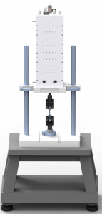
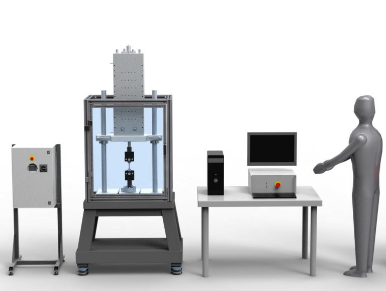
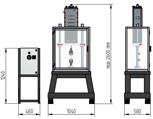
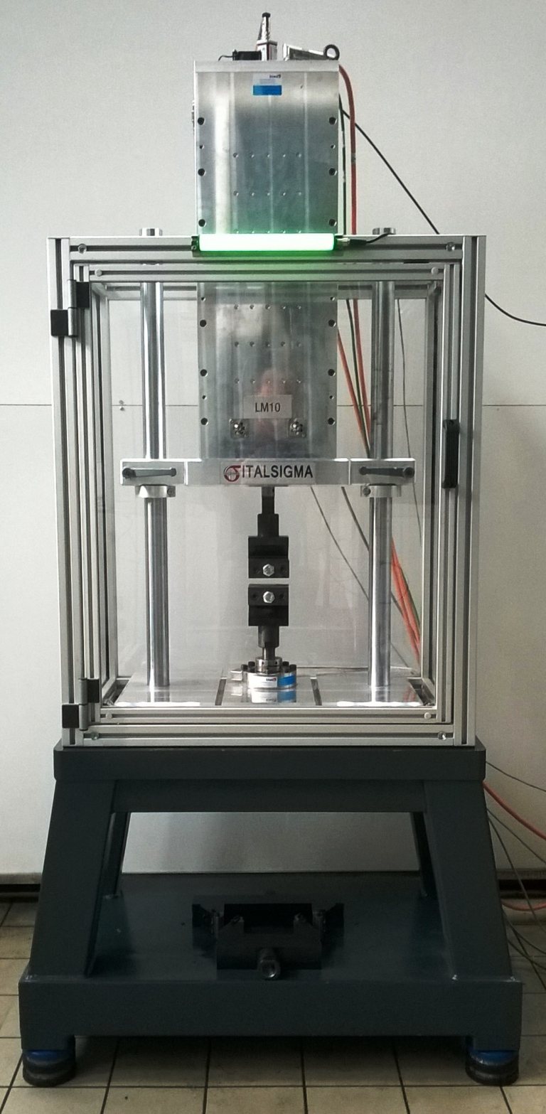
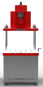
Two-column testing machine equipped with an electric actuator mounted on the upper crosshead and a slotted lower support base.
The load cell can be mounted either on the actuator or on the support base. The machine provides very high dynamic performance, with frequencies of up to 80 Hz.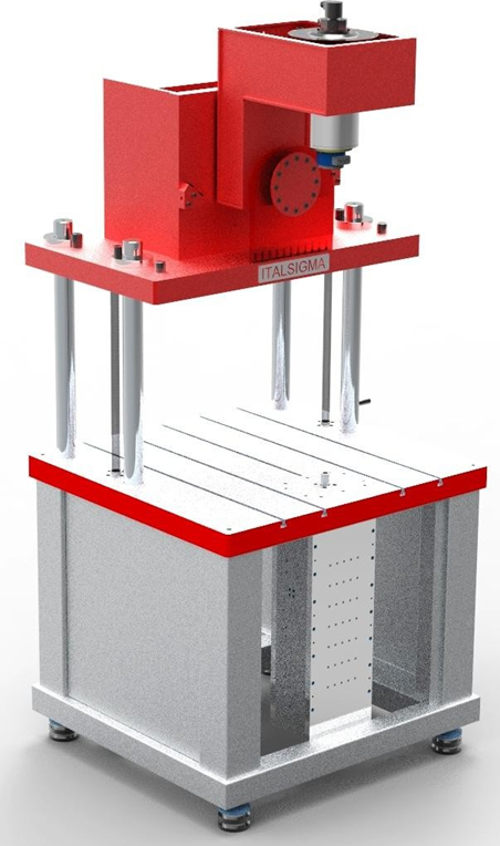
Three-axis biomechanical simulator for orthopaedic prostheses.
The machine features a four-column frame with an electric actuator mounted beneath the lower crosshead. The load cell can be mounted either on the lower or upper test surface. Equipped with a 6-axis load cell measuring Fx, Fy, Fz, Mx, My and Mz. TECHNICAL SPECIFICATIONS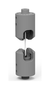
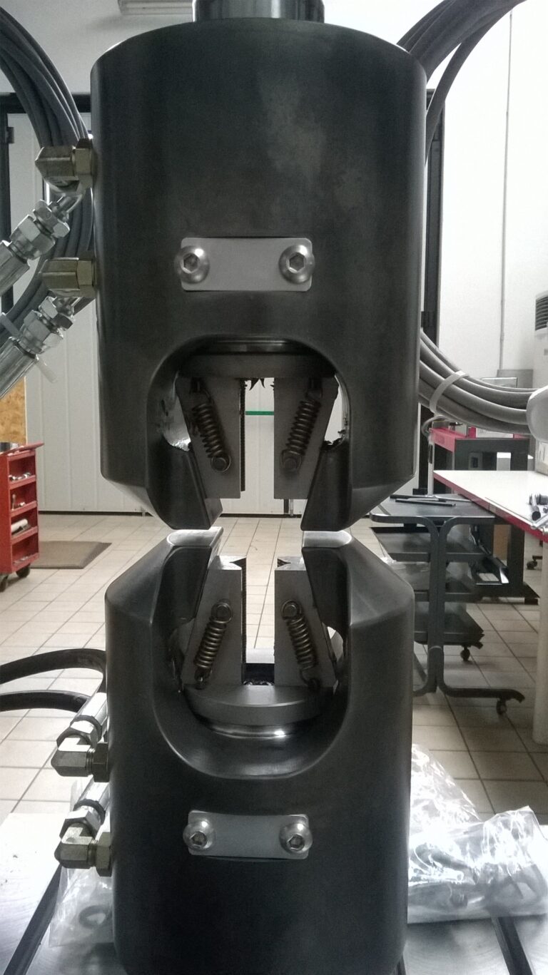
Self-centering hydraulic wedge grips with a one-piece steel body, suitable for tensile and compression testing as well as load cycles around zero, with forces of up to 100 kN.
Supplied with: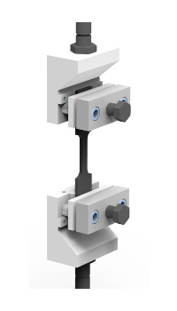
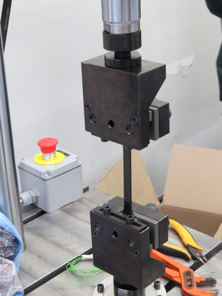
Mechanical grips for flat and/or round specimens, operating on a screw-clamping principle.
The grips are manufactured from 39NiCrMo3 quenched and tempered steel with a blued surface treatment, making them suitable for fatigue testing with loads of up to 20 kN. The gripping surfaces feature a knurled clamping system. Maximum gripping width: 30 mm Supplied with: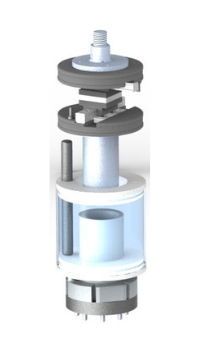
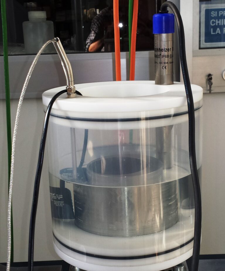
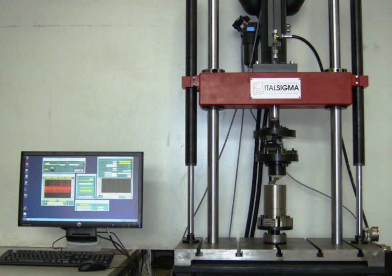
Testing system designed to perform static and fatigue tests on hip prostheses, consisting of:
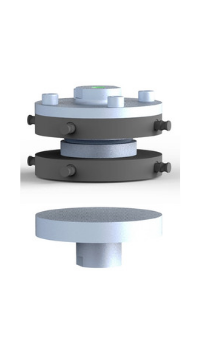
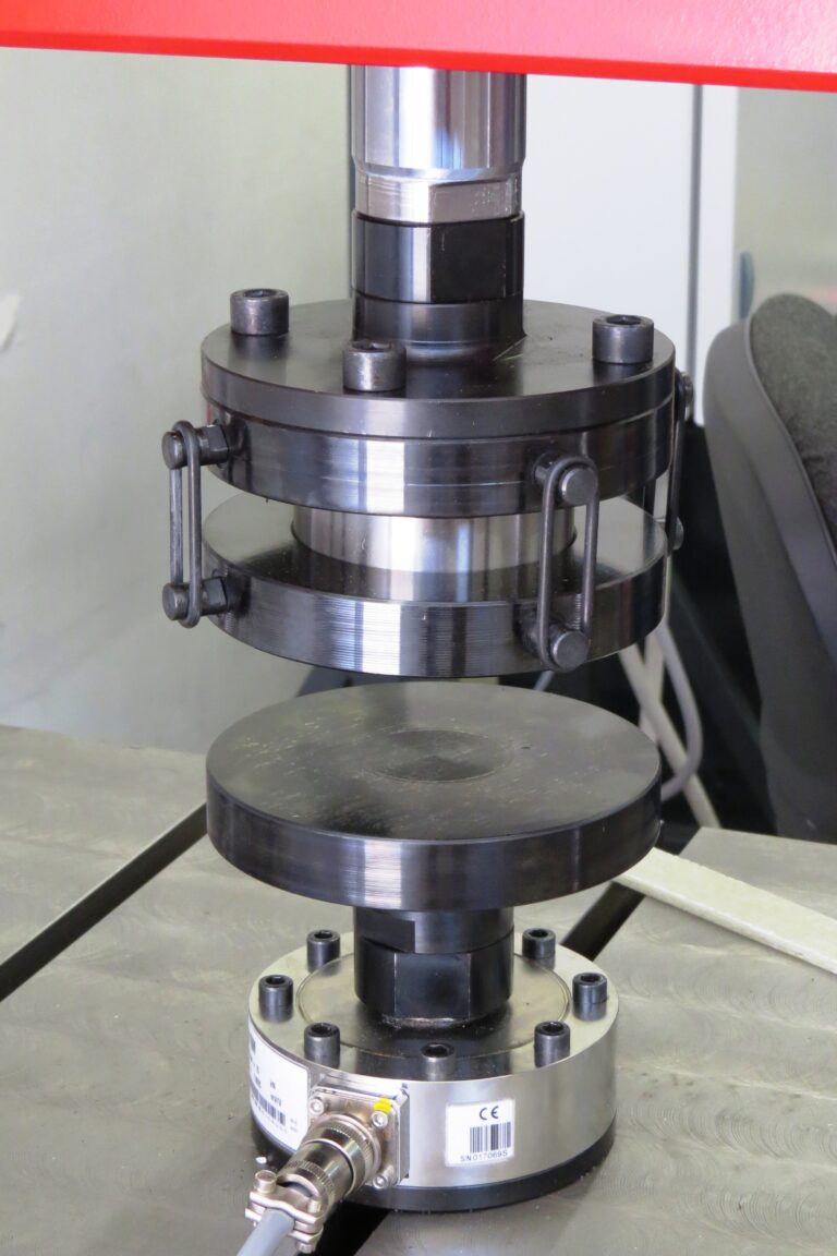
System consisting of circular steel compression platens made of 38NiCrMo3 steel, complete with a spherical joint to compensate for minor misalignments.
The upper platen, equipped with a spherical joint, is directly connected to the actuator piston rod. Four elastic retaining rings keep the spherical joint assembly in position. The lower platen is connected to the load cell, which is in turn secured to the frame base. TECHNICAL SPECIFICATIONS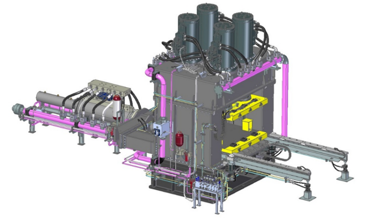
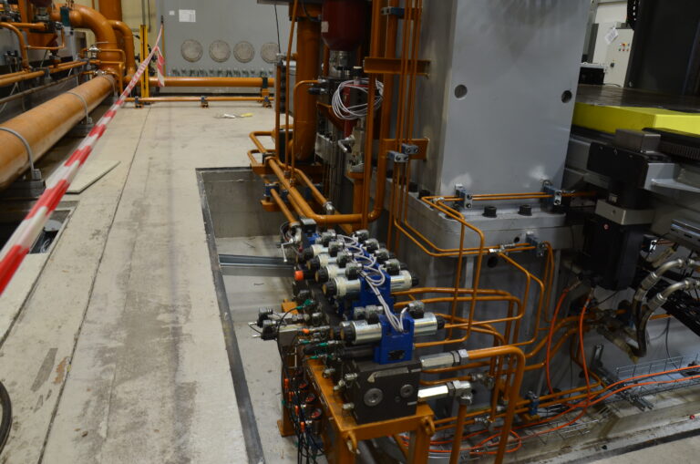
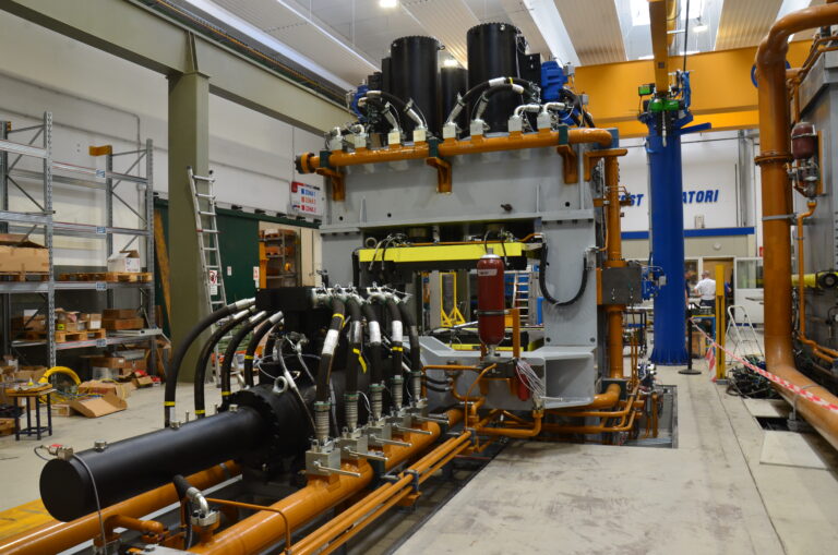
Testing machine designed for testing seismic isolators.
TECHNICAL SPECIFICATIONS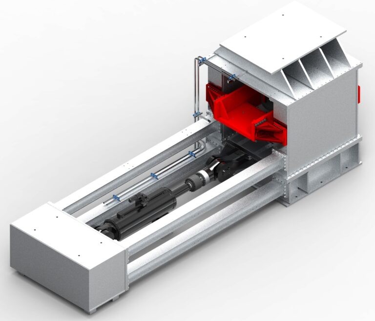
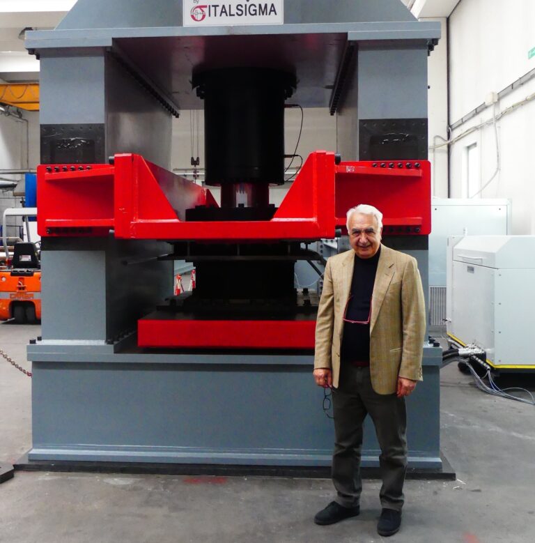
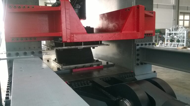
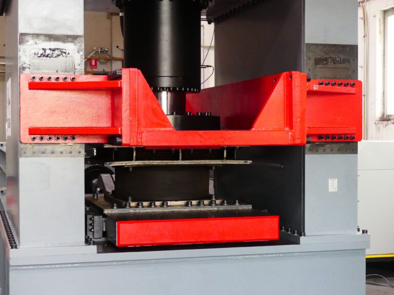
The testing system is designed to evaluate the performance of elastomeric seismic isolators.
The tests involve applying a compressive load in the vertical direction while imposing cyclic horizontal displacements. TECHNICAL SPECIFICATIONS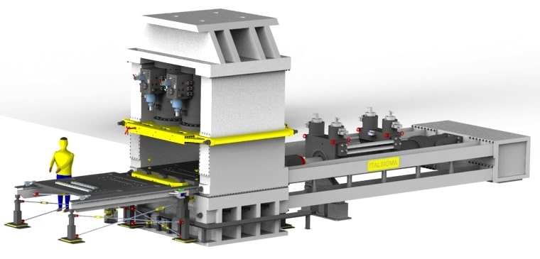
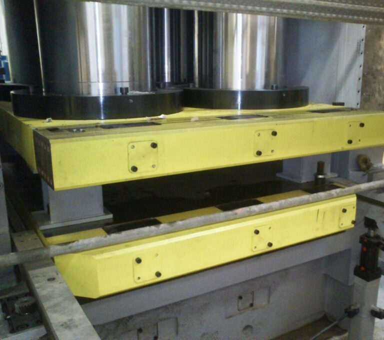
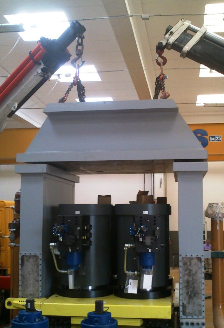
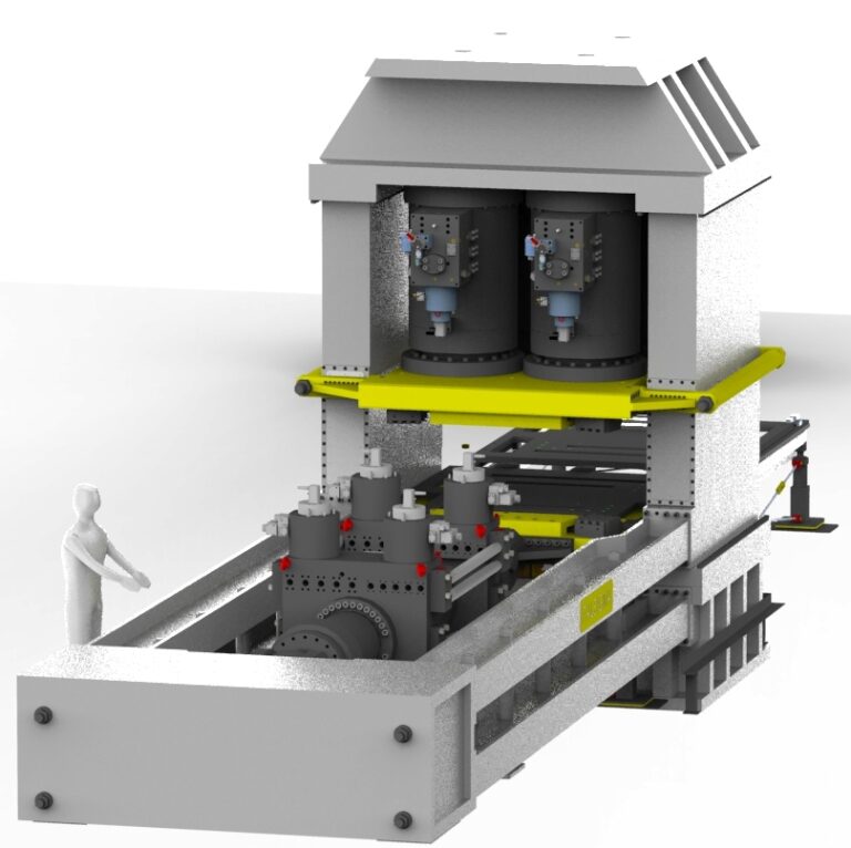
The testing system is designed to evaluate the performance of seismic isolators.
The tests involve applying a compressive load in the vertical direction while imposing cyclic horizontal displacements. The machine's general performance specifications in terms of vertical and horizontal load, displacement and speed have been defined to cover the vast majority of end-of-production tests and most qualification tests. TECHNICAL SPECIFICATIONS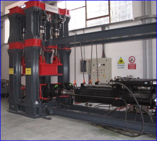
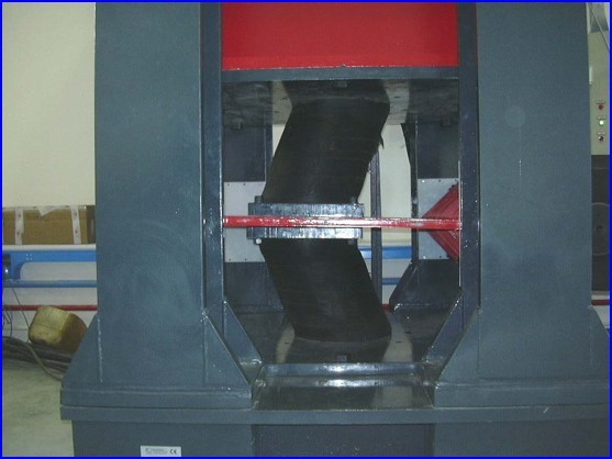
High-stiffness load frame designed to simultaneously apply compression and shear loads in orthogonal directions.
The system can be used to test two-dimensional structural panels, such as walls, as well as structural components such as seismic isolators. Long working strokes can be applied to test components with a low elastic modulus, such as elastomeric bearings. TECHNICAL SPECIFICATIONS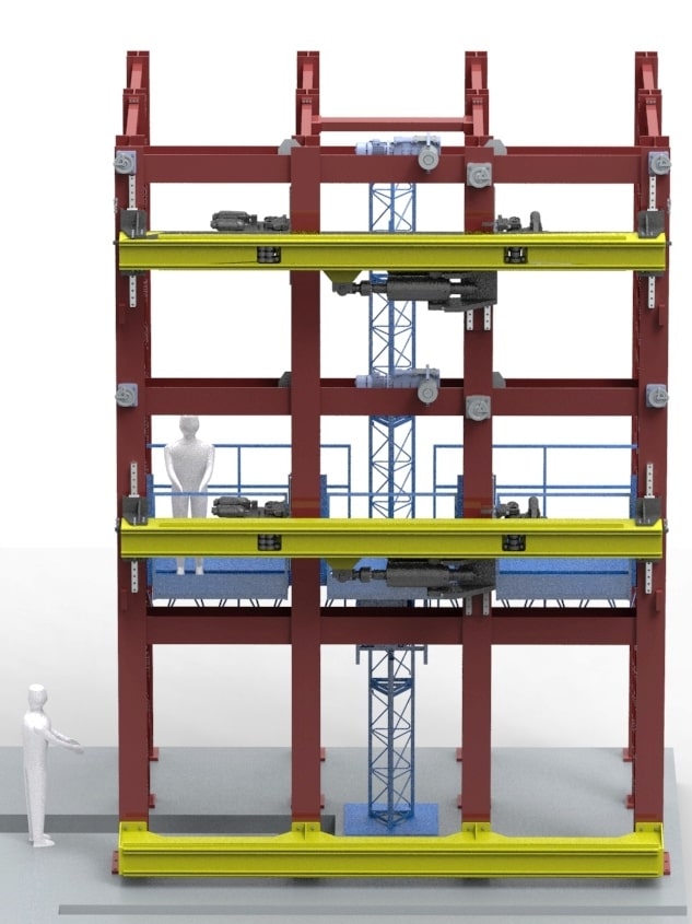
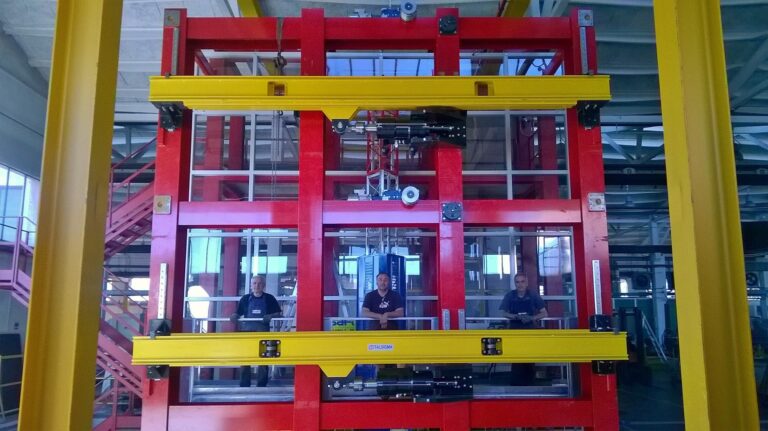
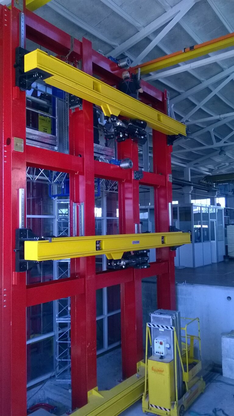
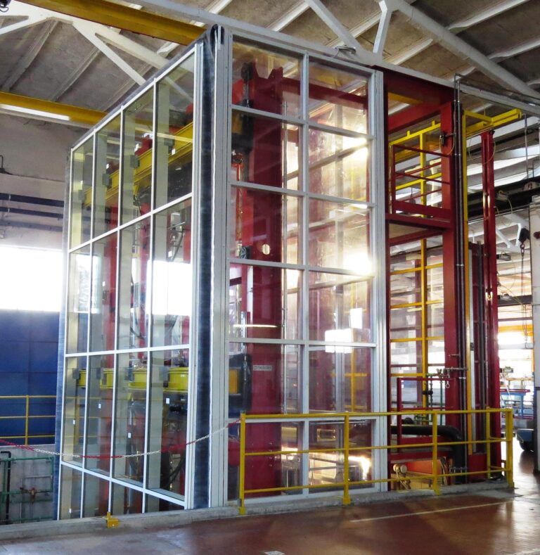
In addition to the traditional air, water and wind tests required for the certification of curtain wall systems, the mechanical testing system allows the seismic response of curtain walls to be evaluated under both static and dynamic conditions.
The system is equipped with seismic actuators capable of applying in-plane and out-of-plane loads to the curtain wall assembly. The system is suitable for: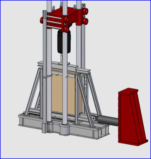
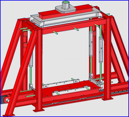
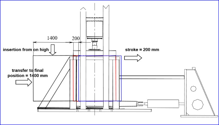
The system consists of a semi-underground foundation connected to a frame for applying vertical loads.
The loading base is equipped with four roller bearings. The lower edge of the wall rests on the roller bearings, allowing the application of shear forces to produce controlled wall distortion. The maximum vertical load is 500 kN. To facilitate installation, the wall is inserted from above and then transferred into its final position using the roller-bearing system.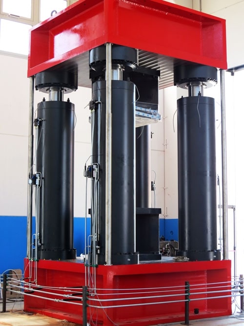
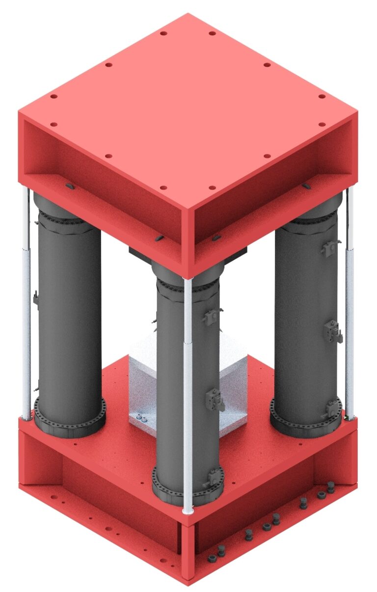
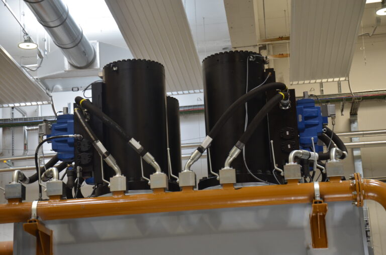
Uniaxial load frame designed to withstand maximum loads of 30 MN in both compression and tension for testing structural components.
The frame is equipped with a fixed lower crosshead and a movable upper crosshead, allowing adjustment of the available test clearance. The upper crosshead is moved by four servo-hydraulic actuators rigidly connected to the two crossheads. These actuators also apply the test load to the specimen by controlling the displacement of the upper crosshead.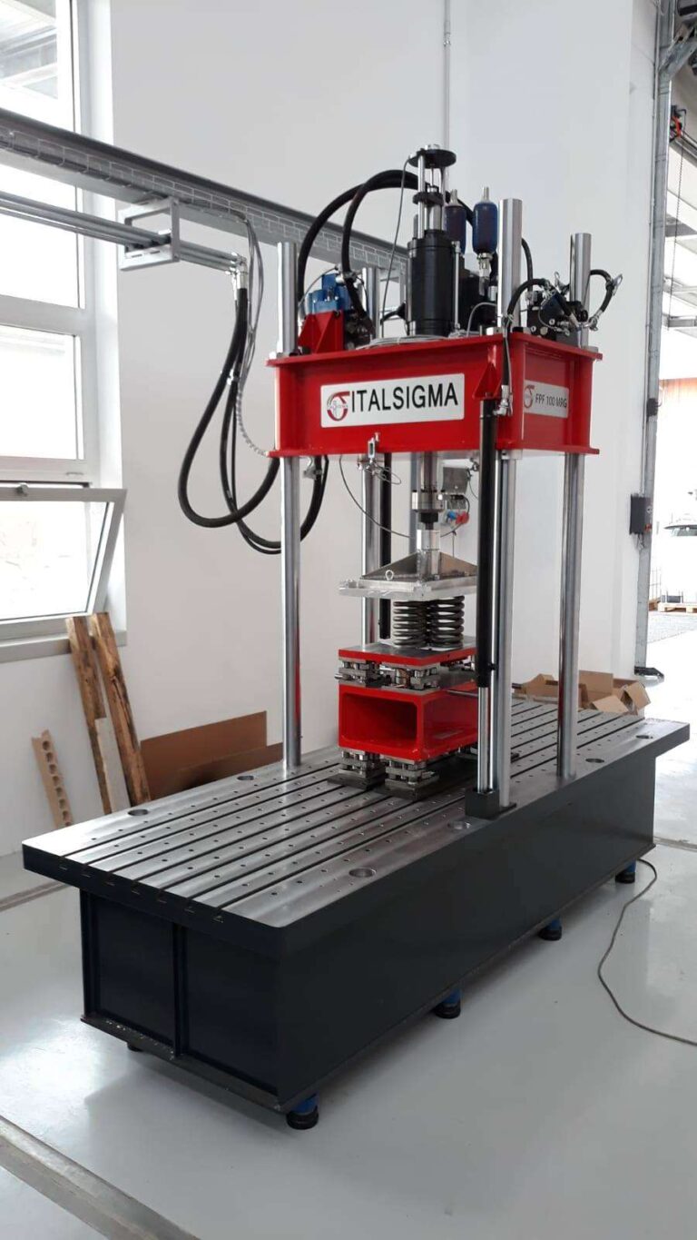
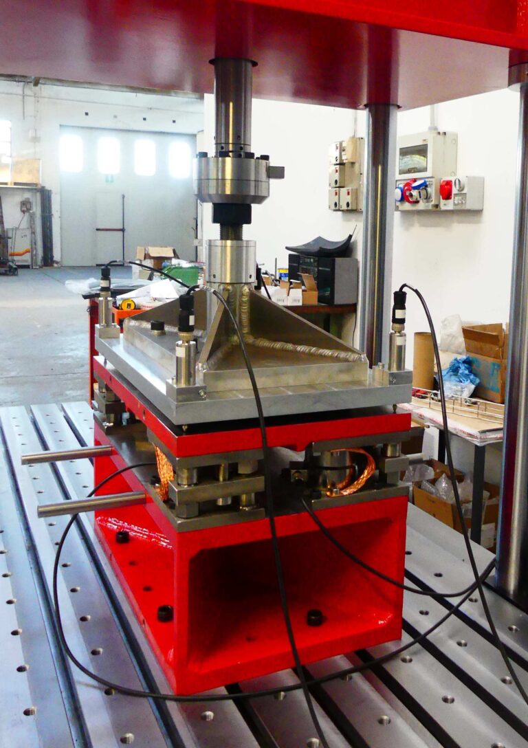
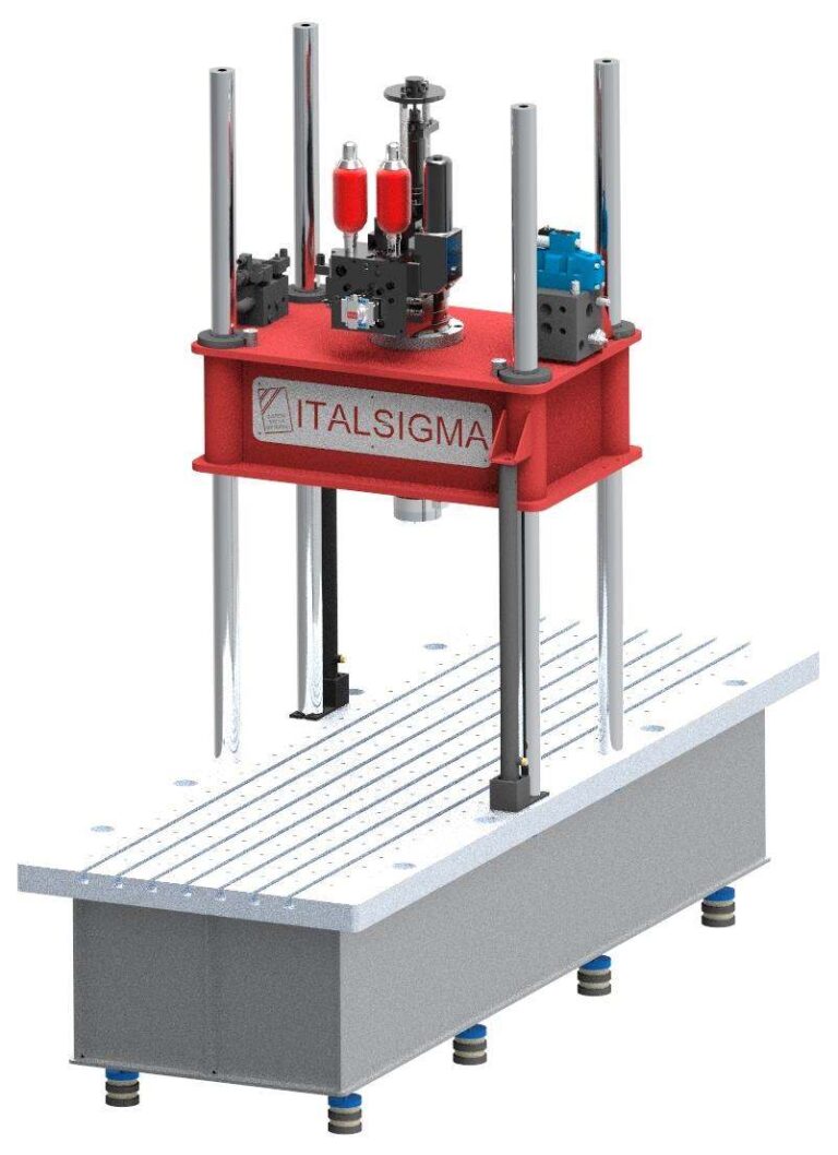
FPF 100 kN – Four-Column Uniaxial Testing Machine for Railway Pad Testing

Holding Company

Sister Company